
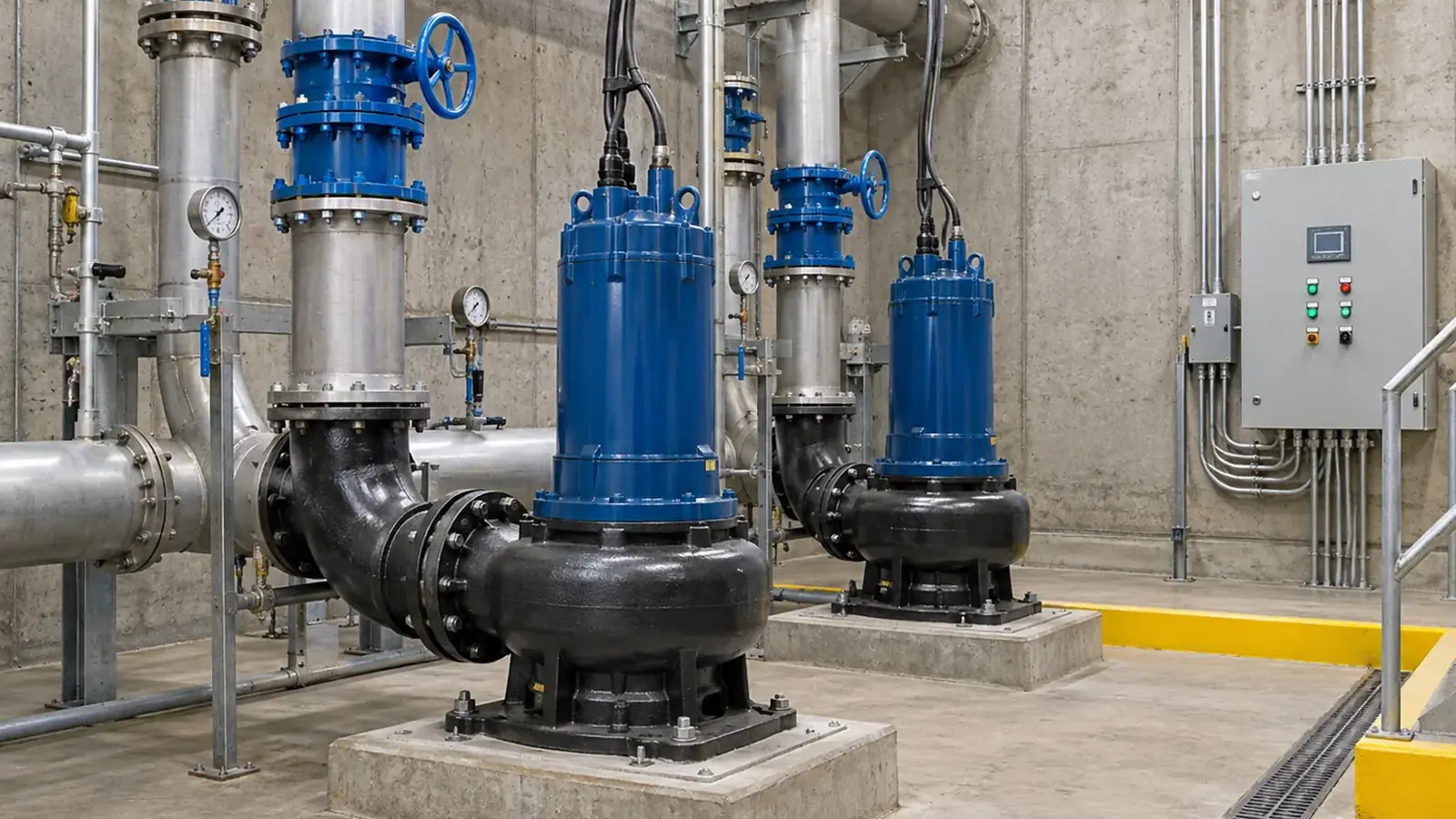
A lift station is a hydraulic, electrical, and operating system. The pump must move the expected wastewater through the force main, but the wet well and controls determine how often it starts, how the station responds to changing inflow, and what happens when equipment is unavailable. Engineering those parts together is more reliable than selecting pumps from peak flow alone.
Establish the inflow and force-main duty
Document current and projected inflow, including normal, peak, and low-flow periods. Identify solids and ragging risk, force-main length and profile, discharge elevation, valve and fitting losses, and any downstream pressure conditions. Compare the resulting system curves with candidate pump curves for one-pump and multi-pump operation.
The design should also consider what happens when a check valve leaks, a force main accumulates air, or one pump loses capacity. Those are operating scenarios, not merely maintenance concerns. A pump that meets one calculated point may not perform acceptably across the actual head and flow range.
Balance wet-well storage and cycling
The wet well provides working volume between control levels. Too little usable volume can lead to frequent starts; too much detention can create odor and solids-management problems. The appropriate volume depends on station configuration, inflow pattern, pump capacity, and constant- or variable-speed control. It should be checked with the proposed start and stop levels rather than copied from another site.
Access and maintainability matter at the same stage. Plan for safe pump removal, guide rails or lifting provisions where applicable, valve access, isolation, instrument service, and a practical path to clean and inspect the wet well. The station needs to be operable when a pump is out of service.
Define pump sequence and failure behavior
For a duplex or larger station, specify lead/lag alternation, lag-pump start, high-level alarm, low-level protection, overload and VFD faults, and the response to a failed level signal. A manual run command does not prove the automatic sequence. The design should state how the station maintains service, alarms, or transitions to a contingency mode after a fault or power interruption.
Pump count and standby capacity depend on the required service level and applicable project requirements. The controls should make the selected arrangement testable. Runtime, starts, levels, motor current, and alarm history are valuable both for commissioning and for later maintenance decisions.
Commission against the design basis
At startup, verify rotation, drawdown or measured flow, force-main and discharge conditions, motor current, level setpoints, lead/lag alternation, high-level alarm, and standby operation. Record the conditions under which the readings were taken. That baseline helps operators identify changes in pump performance, force-main resistance, and controls behavior over time.
An initial project package can include inflow records, force-main drawings, wet-well dimensions, existing alarm history, site photographs, power and controls information, and schedule constraints. RMS Pump can discuss new lift-station pump-system sales and engineering alongside field service, repair, and return-to-service testing for public infrastructure in Oregon and Washington.